I will share personal experience with Yaesu FTDX-10, FT8 and JTDX.
I start by connecting the equipment.
Old radio hams told me that I should make or buy an interface box to connect the computer to the audio input/output of the transceiver, because repair shops were full of transceivers to repair burnt USB ports.
Well, I can also walk to the sea to avoid an accident, but I prefer to “start” the car and walk with it😉.
So I connected the computer and the transceiver via a USB cable.
The USB connection is the easiest way to establish audio channels, CW and PTT signaling and CAT control of the radio from a computer. One USB 2.0 Type-A to Type-B cable replaces all old-fashioned interface boxes, audio cables and RS232 connections. Connect the USB cable between the USB Type-B port on the back of the radio and any USB port on the computer.
You can easily use a USB 2.0 port, it is unnecessary to jump to USB 3.0 – there is no such exchange. But a virtual COM port driver must be downloaded and installed from the Yaesu site.
1. Preparation
I needed:
- Yaesu FTDX-10 transceiver;
- computer with JTDX installed;
- USB cable A/B from an old printer;
- antenna tuner;
- antenna.
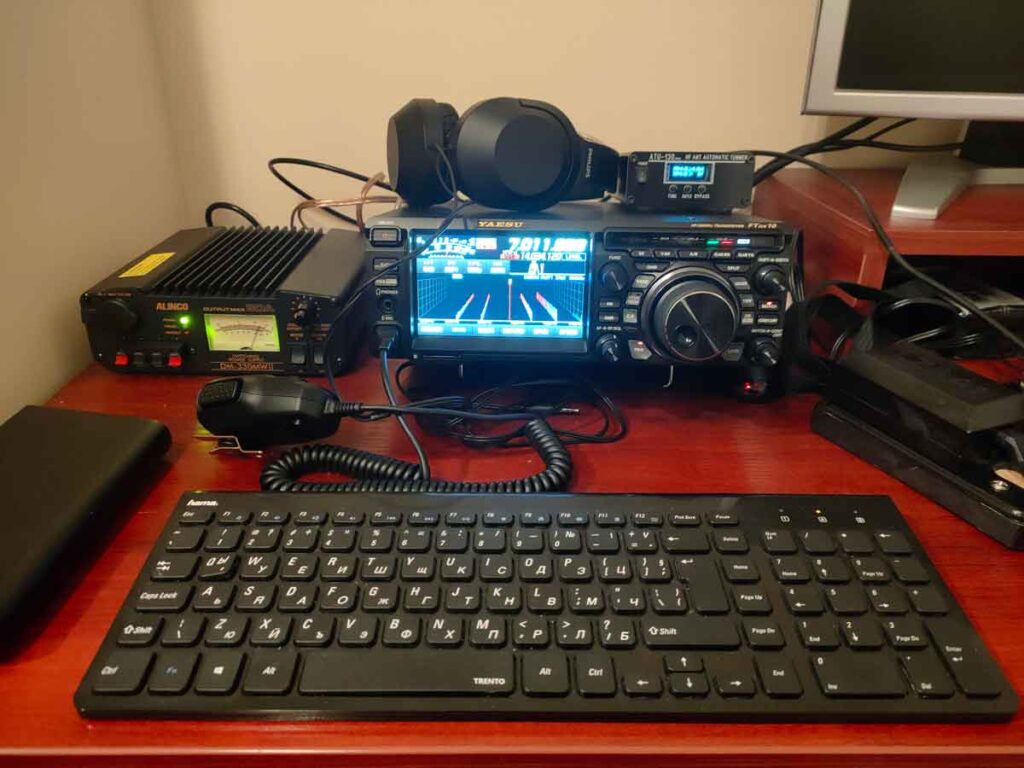
2. Connecting the radio to the PC and the antenna
My antenna is G5RV. I combine it with an automatic ASU “ATU-130” bought from “Ali Express”, which turned out to be a surprisingly good hit for its price. Any other is certainly suitable, but for the G5RV antenna a matching device is absolutely mandatory. The built-in ACS at greater than 3.0 KSV fails to remove it.
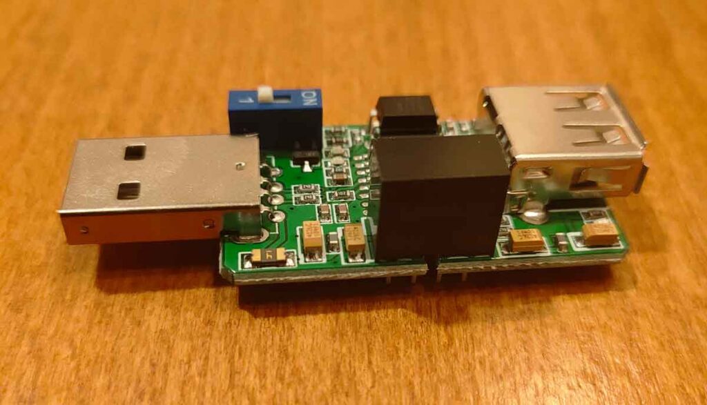
Again from “Ali Express” I bought a USB protection that galvanically separates the computer from the transceiver. Well, at first I worked without it, but the risk is always there, including after I put it on 😉.
The USB cable alone is not enough to make it work, so I had to install drivers.
3. Drivers
I downloaded the drivers from the Yaesu site https://www.yaesu.com/. On the page for the FTDX-10 transceiver, there is a “Files” section, and there is the link FTDX10 USB Driver Virtual COM Port Driver (Windows 11/10) (I’m using Windows 11 and below is a description of it). I downloaded the file “CP210x_Universal_Windows_Driver.zip” from the link.
Important! I unzipped the file to a separate folder on the computer.
Right-clicking on the .inf file (silabser.inf) I selected from the context menu Install and the driver is installed. After installation, I deleted both the file downloaded from Yaesu and the folder where I unzipped it – I don’t need anymore.
After installation, I connected the computer to the transceiver using the USB cable and the shield. When I turned it on, a message appeared that a new device was detected and the driver installation was complete.
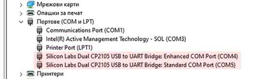
Under “other devices”, two new devices appeared (codec and CP2105 Dual USB to UART Bridge Controller):
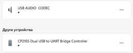
The driver had created two new COM ports – 4 and 5. COM4 was Enhanced, COM5 was Standard. The enhanced COM4 port is used for CAT control of the radio.
I probably would never have guessed that the codec name USB AUDIO CODEC refers to the transceiver, so I renamed the codecs with the more telling (to me at least) name FTDX-10. This happened when in the Windows settings, in the sound section, I selected the input (respectively output) USB codec and clicked on the “Rename” link.
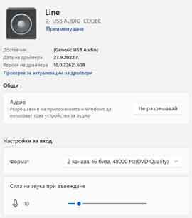
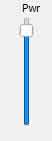
Now I found it convenient to adjust the parameters of the ports and at least roughly the input and output levels. I left the output at level 10-12 at highest quality (16 bit, 48000) and the input at about 30. I left the exact setting for later. The radio does not have a volume control knob via the USB cable, so tuning is done mainly from the computer and somewhat operationally from the JTDX program via the Pwr slider.
I turned off all the additional effects (Enhancements, Spatial Sounds and any other – exactly what is there depends on the sound card of the computer). The goal is to provide a maximally linear and free of other effects sound characteristic in both directions.
Important! The volume control heard from the transceiver does not affect the level of the sound sent to the computer via the USB cable. But noise reduction affects both audio output and USB output.
4. Radio Setup
The following settings apply to the USB cable connection when the radio is in one of the DATA type modes, with a brief explanation of the respective setting.
<FUNC> <RADIO SETTINGS> <MODE PSK/DATA> <DATA MOD SOURCE> <REAR>
DATA MOD SOURCE specifies the plug-in location of the USB cable REAR (ie the rear panel of the transceiver).
<FUNC> <RADIO SETTINGS> <MODE PSK/DATA> <REAR SELECT> <USB>
REAR SELECT specifies the use of USB from the rear panel of the transceiver.
<FUNC> <RADIO SETTINGS> <MODE PSK/DATA> <RPORT GAIN> <12>
RPORT GAIN sets the port gain to 12 (default is 10, I increased it slightly on the recommendation of other digital experts).
<FUNC> <RADIO SETTINGS> <MODE PSK/DATA> <RPTT SELECT> <RTS>
RPTT SELECT sets PTT to RTS switching on the extended COM port.
<FUNC> <OPERATION SETTING> <GENERAL> <CAT RATE> <38400 bps>
CAT RATE is used to set the interface speed of the USB connection. The port speed of the computer and the transceiver must be the same. The default transceiver speed is 38400 bps and I left it that way.
<FUNC> <OPERATING SETTINGS> <GENERAL> <CAT TIME OUT TIMER> <10>
CAT TIME OUT TIMER sets the time the radio will wait for a response to a CAT command. I left it at the default of 10ms.
<FUNC> <OPERATING SETTINGS> <GENERAL> <CAT RTS> <OFF> (default is ON)
CAT RTS is not the PTT control line and I turned it off because some programs are not compatible with CAT RTS ON.
5. Program Setup JTDX
There are a few important initial settings in any program for digital amateur radio operation, without which nothing will work.
I chose JTDX as my main program because it has a number of advantages over WSTJ-X that are appreciated in the process of operation. It’s only downside is that it’s not geared for racing, but I’m not a racing fan anyway – my preference is towards DX.
Of course, it doesn’t hurt to try different programs before choosing yours.
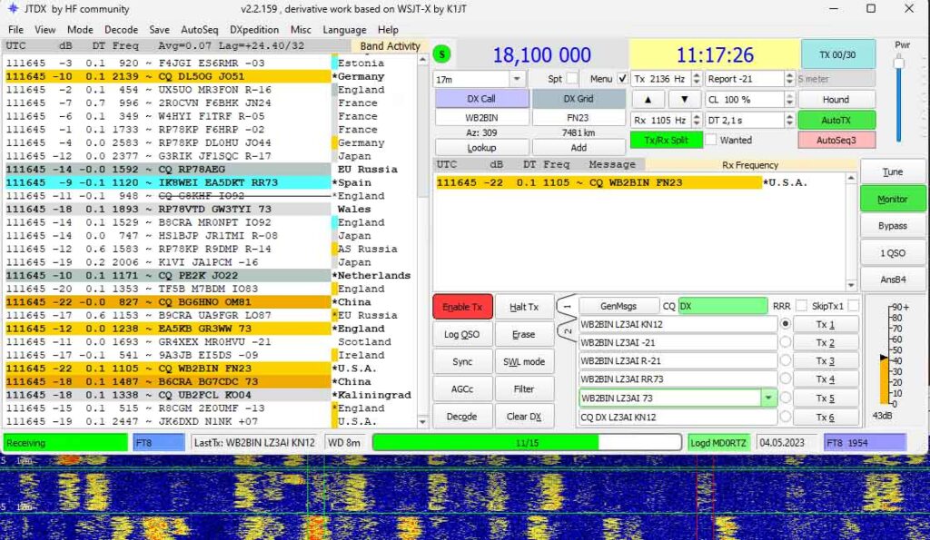
I opened the settings of the JTDX program and already in the General settings tab I entered my callsign, the QTH-locator to the sixth character and the IARU region. Other changes are optional, my preferences can be seen in the screenshot below.
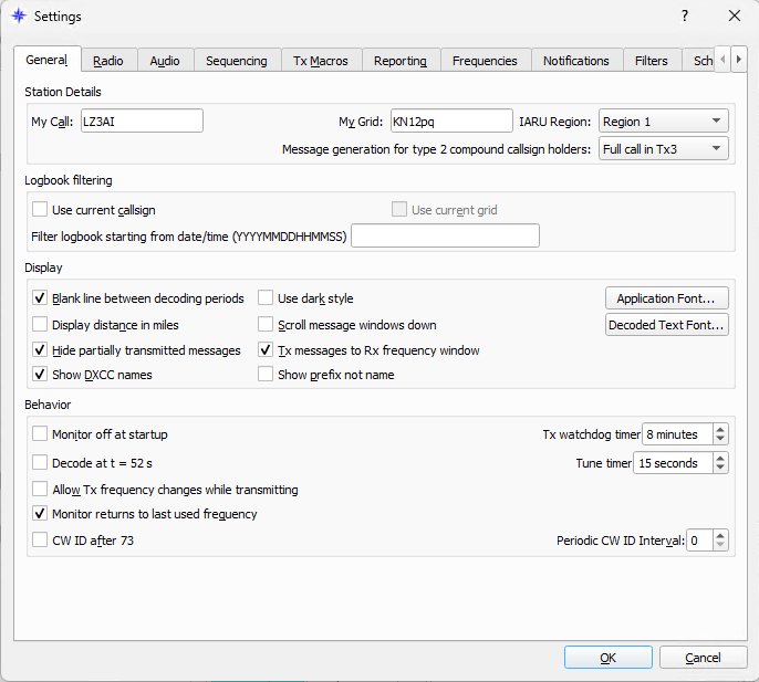
Important: a sufficiently detailed help text appears when hovering over a parameter.
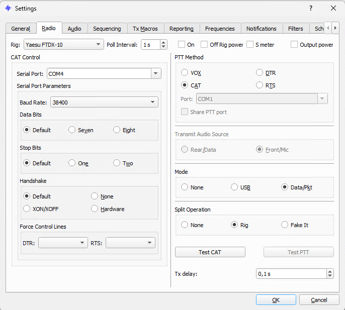
I switched to the “Radio” tab and set the Rig to the Yaesu FTDX10.
- Under the heading “CAT Control” I set the serial port number to the Enhanced Com port. I chose the same baud rate as the one set in the radio. Default is 38400.
- In the field on the right, I checked for PTT method – CAT, for Mode – DATA/Pkt, for Split – Rig, I left the other parameters as default.
I opened the “Audio” tab
- I set the output codec FTDX10 (4- USB Audio Codec) as “Input”.
- I set “Output” to the input codec FTDX10 (4- USB Audio Codec).
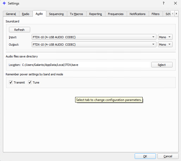
Important: The name of the codecs on another computer may be different.
The other sections at the beginning are not important to get started.
I returned to the “Radio” section to check with the Test CAT and Test PTT buttons whether the computer control of the transceiver was working correctly and whether it was switched on normally for transmission. The Test CAT button turned green, the Test PTT turned red and the radio transmitted – so everything is OK.
The radio frequency is visible off-screen with JTDX and changes synchronously with that of transceivers under both program and radio control.
So far so good. I tuned the radio to the selected frequency for FT8/FT4 and set it to 30-40 watts.
6. Adjust transmit and receive audio levels and noise reduction
I turned the S-meter on the FTDX-10 into ALC mode. According to the literature, the level it shows in this case should be almost or even equal to 0. In my opinion, these are myths. I keep it between 5 and 7 and the signal is free of distortion and no red areas on the correspondent screen.
The transmit signal level is adjusted operationally by the JTDX program’s Pwr slider.
Important: If this slider does not help, the transceiver menu level must be adjusted from the <FUNC> <RADIO SETTINGS> <MODE PSK/DATA> <RPORT GAIN> which I initially set to <12>. This value may need to be different for different computers and sound cards. It may be easier to play around with the level adjustment from the computer’s sound card.
Important: If the level in the computer is too high, the digital mode signal can create harmonics in the audio signal, which can cause the digital mode signal to be transmitted to two frequencies simultaneously. This confuses the correspondent and can make you unpopular.
The transceiver does not have the ability to adjust the output level of the receiver to the computer. Neither does JTDX. So we have to use the setting from the Sound Recording tab of Windows. The optimum level is between 30 and 50 dB and is easily seen in JTDX:
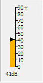
Important: The volume buttons on the radio do not affect the volume level sent via the USB cable to the computer. But the noise reduction affects and we have to be careful with it. It is recommended that it be turned off and that decoding in noisy conditions be left to the computer software.
7. Working with the JTDX program
JTDX is intuitive enough and I don’t think I’ll dwell on it in detail. All buttons and options display sufficiently detailed help text when hovering over them.
But there are three or four things that can be found throughout the texts of job manuals, but which we usually do not pay enough attention to, or, out of old habit, refuse to accept.
- Power. FT8 is a link mode between low power radios and compromise antennas. At first glance, this does not prevent working with high powers, but in practice it is completely unnecessary and interferes with other correspondents (let’s not forget that they all use very close frequencies!). Personally, I work with a power of 20-30 W (current has become more expensive! 😉). If for a particular DX QSO I’m concerned that my power is low, I increase it to 50W, no more. Any more will accomplish nothing but create redundant QRM for neighboring stations and cause them to shift.
- Working with the waterfall. I actively use the waterfall to adjust the baud rate. I listen, I listen, I listen! And I’m listening again! (in this case, I’m looking at the waterfall 😉). I select an entire empty column to put my red “beam” on transmission. If there is no “clean” speaker, I at least put it somewhere with the fewest signals. The green “beam” – the one for acceptance, it doesn’t matter where I put it. Well, if I’m going to call CQ, I also choose a clean speaker for the receive beam, different from the transmit speaker. If an interesting station doesn’t hear me for a long time and its DT is less than 0.3 s, I try to find a clean speaker near its reception frequency to move my transmitter there – I don’t exclude that it forgot to leave the 500 kHz you’re a bandpass filter (because it’s happened to me 😉).
- Beep level. I don’t rely on automatic gain control. I already wrote that I got rid of all equalizers and sound effects – the characteristic of the sound tract should be as linear as possible until it reaches the software. I leave the audio signal low enough to not get any distortion – the FT8 is a mode where this is more important than getting a high enough level signal to the correspondent’s receiver. A good solution for initial setup is if you have a friend who you can talk to and at the same time hear and see the waterfall signal, tell them if they hear it distorted and on the waterfall with bright red spots. Reduce the level until these spots disappear.
- Noise suppression. I’m usually off. There have been cases where I’ve had somewhat better effect with digital noise reduction, but this is very specific and quite rare – the reason being that the FT8 signals themselves often resemble plain background noise.
- Clock. Despite the expectation that everyone knows how important time is to digital modes of operation, there are many radio amateurs who do not keep their clocks as accurate as possible. If a correspondent’s DT is more than 0.3s, I don’t try to contact him at all. If it’s important or rare to me, I use a program JTSync with which I can set my time to be in sync with the correspondent’s and then bring it back to the right time. JTDX also has its own way for such reconfigurations (I think), but I haven’t figured out how exactly it’s done yet, so I prefer JTSync.< /li>
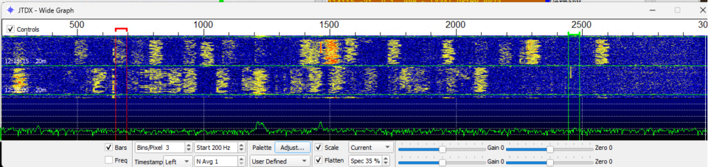
- Filters. I’m careful with bandpass filters. The radio has a wonderful display showing the filtering, so I can immediately tell if my filter is OK or not. I usually use the 3MHz “hardware” bandpass filter for the FT8 and nothing else. I have also tried with 12 MHz, but there is no visible better effect and it seems more logical to work at 3 MHz, especially since the spectrum of my waterfall is not greater than 3
To see a waterfall of about 3 MHz, my settings are like the ones in the next picture.
I’m sure we’ll learn the rest much better as we go along.
73!


One thought on “Yaesu FTDX-10, FT8 & JTDX”
Hello
Well I have to say you are the only person on the web that knows how to tell people how to set up the FTdx10 and the computer… I watched many videos and read many articles and none worked for me… I gave up and my son found your article abt setting it up and had the thing running in abt 40 minutes… I’m going to be using the radio in a remote location 50 km away… Thank you for the great info…
Good DX and 73
Fred W0PE
I have passed your link to a bunch of people…