General Tips
So far we have discussed Telephony and CW carrier behavior in great detail, as these classes of broadcast are by far the most popular with radio amateurs. You have noticed that in general the behavior is the same for both broadcast classes, the differences being mainly in the use of Q-code, fusion characters and specific terminology.
The basic procedures that were discussed for telephony and CW also apply to most other commonly used broadcast classes such as RTTY, PSK(31), SSTV, etc.
Radio amateurs also use highly specialized classes of transmission and communication methods such as Fax, Hell, contacts via Earth satellites, EME (reflection from the lunar surface), reflection from meteor trails, Aurora (reflection from auroras), ATV (broadband amateur television). etc., which more or less require special procedures and we will pay separate attention to them.
What is RTTY
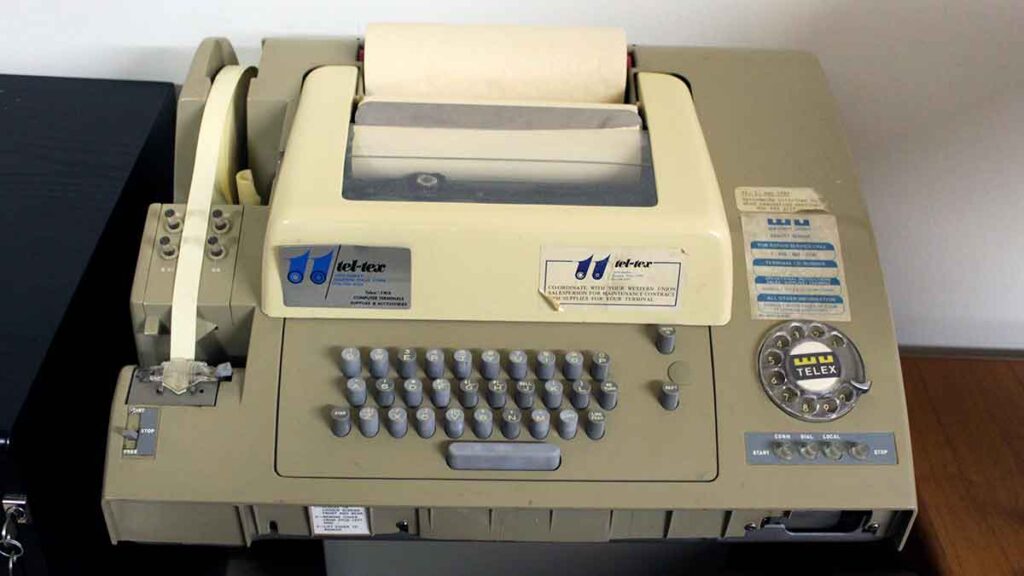
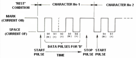
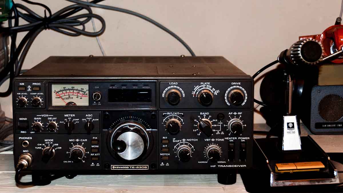
RTTY is the oldest digital broadcast class used by radio amateurs, excluding CW, which is actually also a digital broadcast class. RTTY is used to transmit and receive texts. The code used in RTTY is designed to be machine generated and decoded. Back in the day (the days of telex machines) these were mechanical machines that generated and decoded the Bodo code – the original teleprinting code first introduced in 1870! Each character processed by the machine is converted to a five-bit code preceded by a one-bit start code and terminated by a one-bit end code. With five bits, however, only 32 possible combinations can be formed (25 = 2x2x2x2x2). Since the Latin alphabet contains 26 letters (only uppercase letters exist in RTTY) plus 10 digits and a number of punctuation marks, the Bodo code assigns two different uses to each five-bit combination depending on the register the machine is in at any given time . These registers are called the NUMBERS register and the LETTERS register. If the machine is transmitting letters and needs to switch to digits, it first sends a five-bit code corresponding to a NUMBERS register. This code switches the machine (or software) to the NUMBERS register. If this code is not accepted for any reason, the machine will continue to print letters corresponding by code to the corresponding digits. This is a common mistake and all RTTY operators know it well, for example when receiving an RST report (599 is taken as TOO). Modern RTTYs are almost without exception based on a personal computer with a sound card and the corresponding decoding software.
In amateur bands, the Bodo code is transmitted via the so-called FSK (two-frequency switching). The second frequency is offset from the transmitter’s original carrier frequency by 170 Hz, and the two frequencies are switched by the Bodo code back and forth (called mark and space in RTTY). In the early days of RTTY, the offset was 850 Hz. The Bodo code contains no error correction mechanism. The standard rate on amateur scopes is 45 Baud. At 170 Hz offset, the width of the FSK signal at the -6 dB level is approximately 250 Hz.
Since RTTY is simply switching between two carriers, the load on the amplifier (the final stage) is 100% (versus approximately 50% on CW and between 30 and 60% on SSB depending on the level of the speech processor). This means never attacking the final stage with 100W (100W measured on CW or SSB) if the transmission will last more than a few seconds, but only with 50W RTTY output power.
Frequencies for RTTY
Prior to 2005, the IARU divided amateur bands into subbands according to broadcast class. Since the post-2005 band plans are based on broadcast signal width instead of broadcast class, novice and veteran radio amateurs may find it somewhat difficult to work with this new approach.
Therefore, below we give the subbands most commonly used for this class of broadcast. They can differ slightly from what is given in the band-plans, as we can compare broadcast class with signal width, which is not always obvious. The table below is not intended to replace the IARU band plans.
160 m: 1.838 – 1.840 kHz. Very narrow window and very little RTTY on this range. The entire signal must fit inside. 1.800 – 1.810 kHz is used in the USA (not allowed in Europe).
Frequencies for RTTY activity:
| 80 m | 3.580 – 3.600 kHz. In Japan 3.525 kHz. |
| 40 m | 7.035 – 7.043 kHz |
| 30 m | 10.140 – 10.150 kHz |
| 20 m | 14.080 – 14.099 kHz |
| 17 m | 18.095 – 18.105 kHz |
| 15 m | 21.080 – 21.110 kHz |
| 12 m | 24.915 – 24.929 kHz |
| 10 m | 28.080 – 28.150 kHz |
Everything standard on telephony and CW also applies here.
RTTY is extremely vulnerable to QRM (interference of any kind). Pilapas must be performed frequently at various frequencies to be successful.
Q-codes were originally developed for CW use. Later, radio amateurs began using some of these codes on telephony as well, where they were quickly adopted. Of course, these Q-codes can also be used in the new digital broadcasting classes such as RTTY and PSK, rather than developing new proprietary codes, which would lead to confusion.
In the digital broadcast classes, all computer programs provide the ability to create files of short, preprogrammed messages, such as might be used in a QSO. But as a bad example of their use, some have prepared brags with information about their station and their computer that never ends… Please do not pass on such details unless the correspondent has asked you to. The short “TX 100 W AND DIPOLE” will suffice in many cases. Pass only the information in which the correspondent might be interested. Do not end the QSO with the time, the link number in your log, etc. This is useless information. Your correspondent also has a watch and doesn’t really care how many connections you’ve made so far. Respect him and don’t force him to read any such nonsense.
Typical RTTY connection:
QRL? DE PA0ZZZ
QRL? DE PAOZZZ
CQ CQ DE PAOZZZ PAOZZZ PAOZZZ AR
PAOZZZ DE G6YYY G6YYY K
G6YYY DE PAOZZZ GA (good afternoon) OM TKS FER CALL UR RST 599 599 NAME BOB BOB QTH ROTTERDAM ROTTERDAM HW CPI? G6YYY DE PAOZZZ K
PAOZZZ DE G6YYY GA BOB UR RST 599 599 NAME JOHN JOHN QTH LEEDS LEEDS PAOZZZ DE G6YYY K
G6YYY DE PAOZZZ TKS RPRT JOHN STN 100 W ANT 3 EL YAGI AT 18 M WX RAIN PSE QSL MY QSL VIA BURE
Rated RTTY transmission frequency
Two definitions have long been introduced:
- The frequency of the sign signal determines the nominal frequency of the RTTY signal.
- The sign signal must always be transmitted on the higher frequency.
If you are listening to an RTTY signal, how can you determine which of the two tones is the sign signal? If it is a USB signal (upper sidebar), the sign signal is the signal that is heard with a higher audio tone. With LSB (lower sideband), the opposite is evident.
RTTY is established in the transmitter usually in one of three ways (both are variations of the second):
- FSK (switching between two frequencies): The carrier is shifted according to the modulation (character or interval). RTTY is actually FM (frequency modulation). All modern transceivers have an FSK option in the broadcast class switch. All of these transceivers display the correct frequency on the digital display (which is the sign frequency) provided the modulating signal (Bodo code) is of the correct polarity. You usually have the option to swap the logic polarity either in the RTTY program or in the transceiver or both (normal and inverted positions). If not set to true, you will transmit a negative signal (upside down!)
- AFSK (Audio Two-Frequency Shift): In this method, the Bodo module code and a generator that produces two audio tones, one for a character and one for an interval. But these audio tones can be suppressed by the transmitter’s audio filters. Modern RTTY computer programs generate these two tones using a sound card. The SSB transmitter is then modulated with them.
-
- on USB: in this method, the transmitter, in the upper sideband position, modulates with the AFSK tones. Let’s say you’re broadcasting on 14.090 kHz (the zero-beat frequency of the SSB suppressed carrier). If you modulate your transmitter with two audio tones, for example 2.295 Hz for a character and 2.125 Hz for an interval, the character signal will be broadcast at 14.092.295 kHz and the interval signal at 14.092.125 kHz. This satisfies the definition (sign of the higher frequency). But note – the transmitter will show 14.090 kHz on the display. If the modulation is correct (tones not swapped) and in case you are using 2.125 Hz (interval) and 2.295 Hz (sign), you simply add 2.295Hz to the SSB report on the display (the nominal SSB frequency) to obtain the nominal RTTY frequency.
- on LSB: same as above, but broadcast is on LSB. Here both transmitted frequencies are below the suppressed carrier frequency. If we use the same mark and gap frequencies as with USB (mark = 2.295 Hz and gap = 2.125 Hz), the mark signal will now be 14.090 – 2.295 = 14.087.705 kHz and the gap signal at 14.087.875 kHz. This does not satisfy the definition of the sign signal always being at the higher frequency. So we need to swap the LSB modulating audio tones. Note that here too the transmitter display will show 14.090 kHz! In this case (now 2.125 Hz is the sign signal and 2.295 Hz is the interval signal) we must subtract the sign signal frequency from the nominal SSB frequency to obtain the nominal RTTY frequency. Using the same example: 14.090 – 2.125 = 14.087.875 kHz.
Why is it so important to know the correct nominal frequency? Imagine you want to see an RTTY station in a DX cluster, it’s better to have the correct frequency, not something that might be a few kilohertz off.
Another reason is that you need to be in the frequency subband specified by the IARU band plan for RTTY. Example: according to the band plan, the interval 14.099 – 14.101 MHz is reserved for radio beacons (eg the NCDXF radio beacon network). This means that if you are using AFSK with 2.125 Hz (interval) and 2.295 Hz (sign) as USB modulation tones, you should never transmit at a display reading on your transmitter higher than 14.099,000 – 2.295 = 14.096. 705 kHz. Considering the effect of sidebands, it is safe to round this number to 14,095.5 kHz.
Why are such high frequencies (2.125 and 2.295 Hz) used for the AFSK generator? To achieve maximum attenuation of harmonics at these frequencies by not passing them through the SSB filter.
If at all possible, use your transmitter on FSK rather than AFSK when creating the RTTY signal. In most cases, the quality of signals generated with FSK is far better.
What is AFSK?
AFSK stands for “Audio Frequency-Shift Keying”. In other words, RTTY is used through the audio input and output of the radio. A modem or appropriate software for a computer and its sound card is used.
Frequencies for AFSK
It should be noted that most SSB equipment displays the frequency of the suppressed carrier as the operating frequency. In such a case, it is necessary to calculate the exact frequency “manually”.
For example, if you operate at 14.083 MHz with a modulation frequency of 2125 Hz, the actual frequency will be 14.083 MHz + 2.125 MHz, or 14.085125 MHz.
Frequencies for AFSK activity:
| 80 m | 3.580 – 3.600 kHz. In Japan 3.525 kHz. |
| 40 m | 7.035 – 7.043 kHz |
| 30 m | 10.140 – 10.150 kHz |
| 20 m | 14.080 – 14.099 kHz |
| 17 m | 18.095 – 18.105 kHz |
| 15 m | 21.080 – 21.110 kHz |
| 12 m | 24.915 – 24.929 kHz |
| 10 m | 28.080 – 28.150 kHz |
Features in AFSK
Transmitter power is reduced to 25-50% of that normally used on CW for safety reasons for the final stage.
