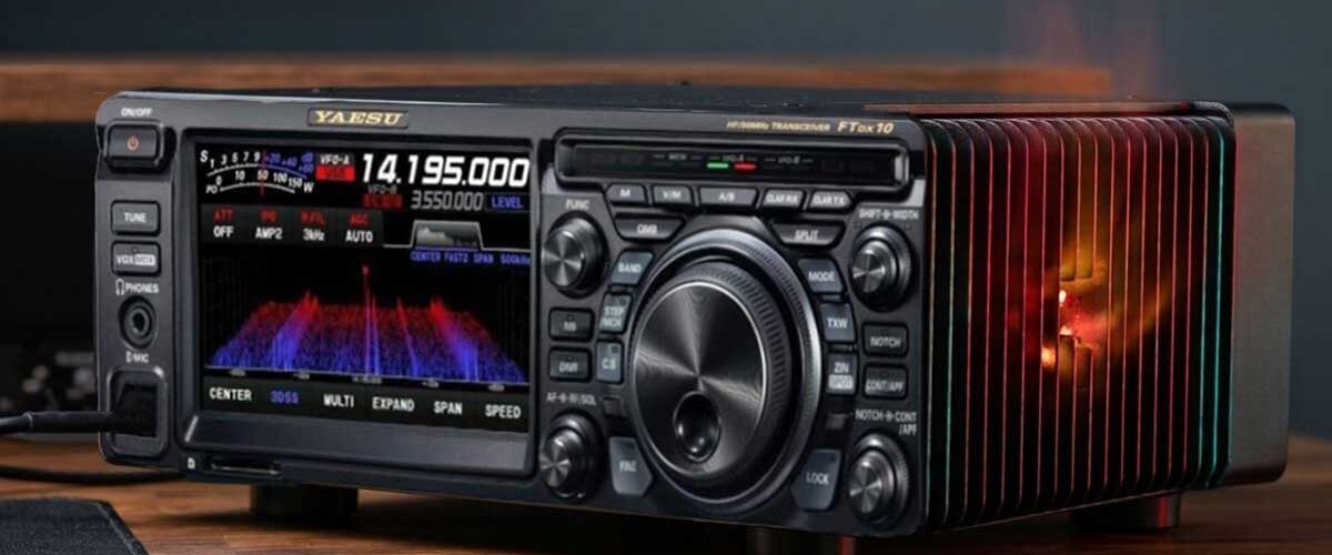
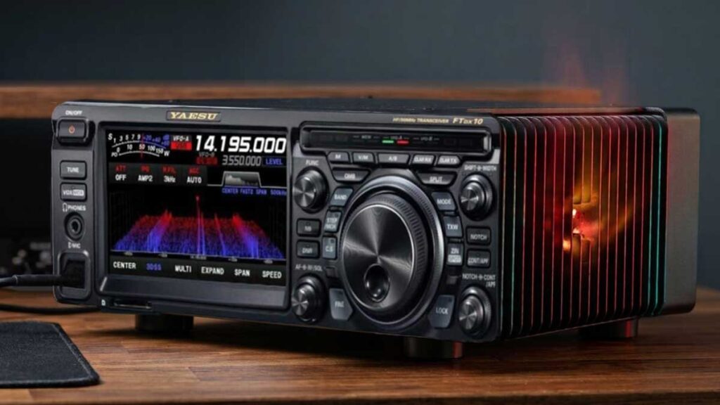
Why Running 100 W on FT8 Is a Bad Idea: The Hidden Risk to Your Yaesu FTDX10 Final Stage
A practical look at thermal stress during digital modes and how to set your transmit power properly.
Why Running 100 W on FT8 Is a Bad Idea
Recently, I had to get the final PA transistors of my Yaesu FTDX10 replaced at the Integra-A service center. It turned out that even from the factory, they had not been mounted with ideal thermal contact to the heatsink. As a result, after about two years of intensive operation—mostly on CW and a substantial share on digital modes (FT8/FT4/FT2)—they simply overheated and failed.
Even though I have always kept this issue in mind and operated digital modes mostly at 33 watts, it still happened. Why 33 watts specifically? Honestly, I don’t know—I just like the number 3… 😉
This turned out not to be an isolated incident. Many fellow hams buy a 100-watt transceiver assuming that because the manufacturer printed „100 W“ on the box, the radio can run full power around the clock in DATA-U mode. In digital communications, however, the physics of thermal load is completely different, and ignoring it often ends with a trip to the repair shop. In my case, the final transistors had also been mounted rather carelessly at the factory—which I find a bit surprising, though not impossible. Perhaps it was a Friday afternoon right before the weekend and the assembler had other priorities on their mind.
The Difference Between SSB/CW and Digital Modes
To understand why the final stage (built in the FTDX10 around a pair of RD100HHF1 MOSFET transistors) experiences so much stress, we need to look at the duty cycle:
The 100 W peak output is reached only for fractions of a second on voice peaks. The average thermal power dissipated by the transistors is barely 20–30%.
Between dits, dahs, and words, there are constant pauses during which the transmitter rests.
The transmitter emits a continuous tone at 100% maximum power for 15 seconds (on FT8) or 7.5 seconds (on FT4), followed by just 15 seconds of rest (or only 7.5 seconds on FT4). If you are running an automated sequence or calling a DX station for an hour straight, the final stage operates at its thermal limit with no real time to cool down.
⚠️ Where Is the Trap?
The transceiver’s thermal sensor measures the temperature of the massive aluminum heatsink, not the silicon die inside the transistor itself. If the factory thermal paste is applied unevenly or the clamping pressure is less than perfect, the silicon die overheats locally long before the heatsink warms up enough to trigger the cooling fan at full speed.
How Many Watts Do You Actually Need on FT8/FT4/FT2?
In amateur radio practice, we often forget the logarithmic scale of decibels. The difference between 30 W and 100 W is barely 5.2 dB—that is less than a single S-unit on your correspondent’s S-meter.
FT8 is a weak-signal protocol designed to decode stations well below the noise floor (down to -21 / -24 dB, and with JTDX even down to -26 dB). In 95% of cases, if propagation supports a QSO at 100 W, you will complete it just as easily with 25–35 W. The difference is that at 30 W your transceiver runs cool, linear, and distortion-free, while your power supply and antenna tuner are spared unnecessary strain.
Running a full 100 W only makes sense for brief moments when chasing a tough DX station in a dense pile-up. Personally, I would bump my power up to 73 W, and in really tough conditions up to 88 W—fellow hams will know why 😉. I reserved the full 100 W almost exclusively for CW.
How to Reduce Power Properly
One of the most common mistakes is throttling output power using the Pwr slider inside the software (JTDX or WSJT-X) while leaving the transceiver set to 100 W. This degrades the signal-to-noise ratio in the audio chain and leads to unstable ALC behavior.
The proper sequence on the Yaesu FTDX10 is as follows:
1. Calibrate the Audio Level (ALC)
In DATA-U mode, press the Tune button in your software and adjust the computer’s audio output level (and/or ‹FUNC› → ‹RADIO SETTING› → ‹MODE PSK/DATA› → ‹RPORT GAIN›) so that the ALC meter on the radio’s display stays strictly within the white zone without exceeding it. This ensures a clean signal free of spurious harmonics. Keep the software Pwr slider around 90% (not maxed out, yet high enough not to destabilize ALC).
2. Limit Output Power Directly on the Radio
Set ‹FUNC› → ‹RF POWER› to 25 W – 35 W. For added convenience, you can assign RF POWER to the programmable ‹CS› button so you can adjust power in seconds with one press and a turn of the outer ring (handy if you change power frequently; personally, I prefer assigning waterfall noise floor level to ‹CS›).
3. Monitor SWR and Airflow
Make sure your antenna is well matched (SWR below 1.5:1) and never enclose the transceiver in tight shelves or cabinets that restrict airflow around the rear panel.
Recommended Settings for Safe DATA-U Operation
- Operating Mode:
DATA-U(upper sideband across all FT8/FT4/FT2 bands). - Rear Audio Input Gain:
‹FUNC› → ‹RADIO SETTING› → ‹MODE PSK/DATA› → ‹RPORT GAIN›→ 50 (default; fine-tune alongside your PC soundcard level). - Transmit Passband:
‹FUNC› → ‹RADIO SETTING› → ‹MODE PSK/DATA› → ‹TX BPF SEL›→ 50-3050Hz (or 100-2900Hz). - Transceiver RF Output:
‹FUNC› → ‹RF POWER›→ 25 W – 35 W (up to 73–88 W briefly when needed). - Software Pwr Slider & ALC: Keep JTDX / WSJT-X
Pwrat ~90%; keep the radio’s ALC bar strictly within the white zone.
Take care of your gear the same way you take care of the cleanliness of your signal on the air. A cool, properly calibrated transceiver will serve you faithfully for years without forcing you to find out firsthand what a fresh pair of final transistors costs.
73 and see you on the bands!
Tony, LZ3AI